
Introduction
Selecting the right MPO fanout cable is essential for building reliable, organized, and scalable fiber optic networks. These assemblies are widely used in data centers, telecommunications facilities, enterprise networks, and other environments where multiple optical fibers must connect through limited space, supporting modern fiber optic networks.
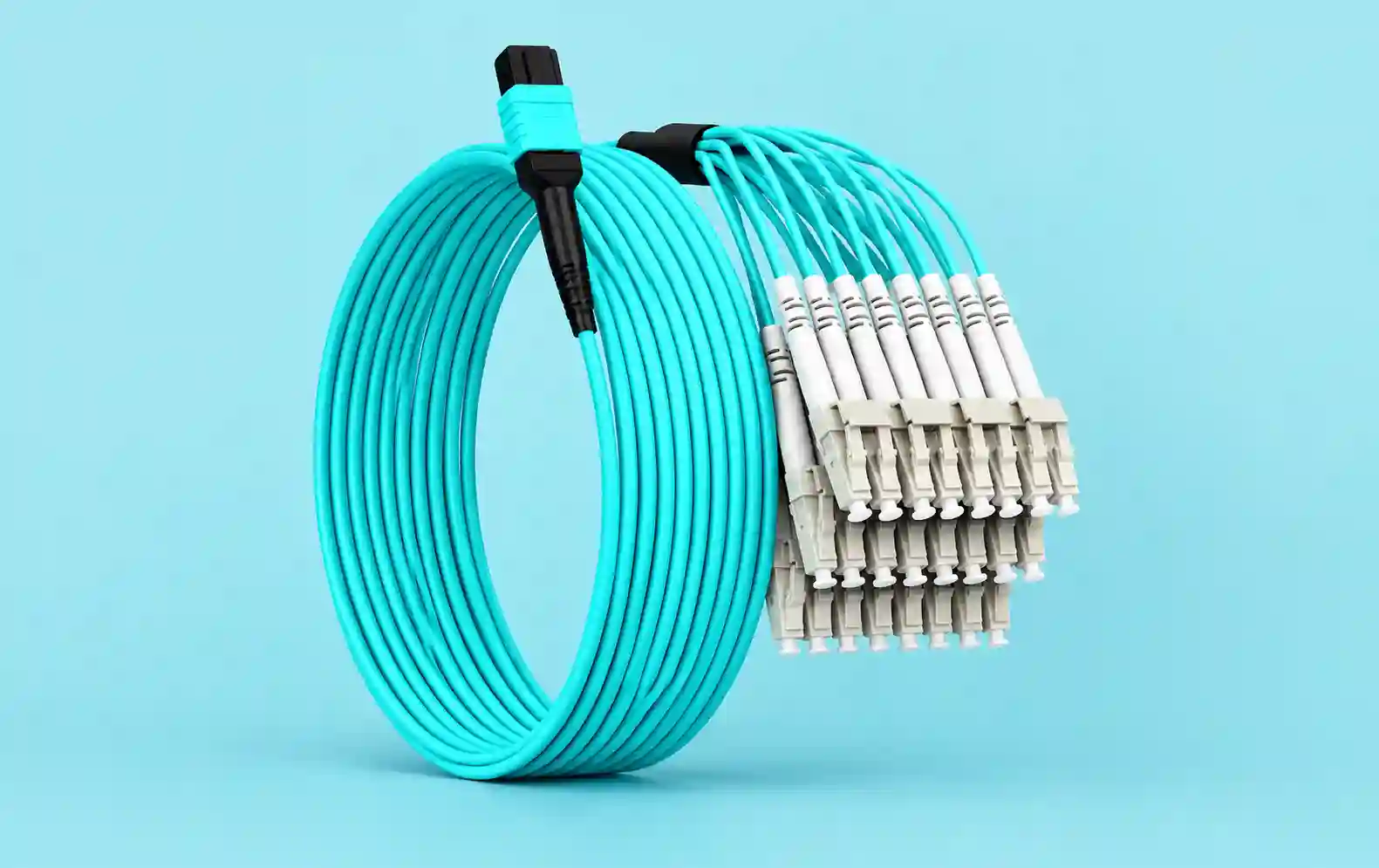
An MPO fanout cable connects a multi-fiber MPO interface to individual optical branches, commonly using LC or SC connectors. This configuration can simplify connections between high-density fiber infrastructure and equipment with individual optical ports.
However, choosing a suitable assembly requires more than matching the connectors at both ends. Fiber count, polarity, connector gender, fiber type, cable length, insertion loss, and installation conditions all influence compatibility and performance.
Identify the Network Application
The first step in selecting an MPO fanout cable is identifying where and how it will be used. A cable designed for a data center switch may have different requirements from an assembly used in a telecommunications distribution frame or laboratory testing environment.
Determine which devices will be connected, what optical modules they use, and how the fibers must be mapped between interfaces.
For example, a network may require one MPO connector to connect to several duplex LC ports. Another application may need individual fibers for patch panels, testing equipment, or specialized distribution systems.
Documenting the connection requirements before contacting suppliers helps prevent incorrect purchases and installation delays.
Select the Correct Fiber Count
MPO connectors are available in different fiber-count configurations, including common 8-fiber, 12-fiber, and 24-fiber formats. The correct option depends on the equipment interface and the required optical architecture.
An MPO connector’s fiber count does not necessarily equal the number of active transmission channels. Some systems use only selected fiber positions, while others use a different arrangement.
For example, a compatible eight-fiber parallel-optics interface may use an MPO-to-four-duplex-LC configuration. Other applications may require different branch counts or fiber mappings.
Buyers should check the transceiver documentation and network design rather than assuming that every MPO cable with a particular number of fibers will work with their equipment.
Choose the Right Connector Types
Connector selection determines whether the cable can physically connect to the intended devices or distribution components.
MPO-to-LC fanout assemblies are common when connecting a multi-fiber interface to equipment with LC ports. MPO-to-SC configurations may be appropriate for certain existing network installations or distribution systems.
The connector specification should include the exact interface type and any relevant compatibility requirements. MPO connector gender, pin configuration, and mating hardware must be checked carefully.
The branch ends also need to match the destination ports. An LC duplex connector, for instance, groups two optical fibers into one connector housing, whereas simplex connectors provide individual fiber connections.
Never assume that two connectors are compatible simply because their general names appear similar.
Understand Cable Polarity
Polarity describes the relationship between the fiber positions at each end of an optical link. Correct polarity ensures that the transmit and receive paths connect as required by the network architecture.
MPO systems can use different polarity methods, and the required arrangement depends on the equipment, trunk cabling, and intended connection.
An MPO fanout cable with the wrong polarity may fit into the ports but still fail to establish a working optical link. This is one reason why cable selection should be based on a complete end-to-end fiber map.
Before ordering, confirm the required polarity with the network design or equipment documentation. If the installation uses existing MPO trunk cables, include their configuration in the compatibility review.
Clear labeling and polarity testing can also help prevent mistakes during installation and future maintenance.
Decide Between Single-Mode and Multimode Fiber
Fiber type is another important specification. MPO fanout cables are available with single-mode and multimode fiber, and the two are intended for different optical applications.
OS2 single-mode fiber is commonly used in networks requiring suitable single-mode optical connectivity. Multimode options such as OM3 and OM4 are used in supported short-reach applications, including some data center links.
The choice depends on the transceivers, transmission distance, channel requirements, and installed cabling system. Using the wrong fiber type can lead to incompatibility or unsatisfactory optical performance.
When upgrading a network, check the existing fiber infrastructure and the requirements of the new optical modules before ordering replacement assemblies.
Evaluate Insertion Loss and Optical Performance
Insertion loss is the reduction in optical power caused by components along the fiber link. Each connector and connection point contributes to the channel’s overall loss budget.
An MPO fanout cable should meet the optical performance requirements of the intended application. Low-loss assemblies may be beneficial when the system has a limited loss budget, but the correct specification depends on the complete optical channel.
Buyers should request test documentation appropriate to the project. Depending on the supplier and assembly, this may include insertion-loss results, polarity verification, and other relevant quality checks.
Connector cleanliness is also essential. Dust and contamination can affect performance and potentially damage connector end faces. Inspect and clean connectors using approved fiber-optic procedures before connection.
Select the Appropriate Cable Length
Cable length affects installation convenience, routing, and cable management. An assembly that is too short may create tension on connectors, while excessive length can create congestion inside racks and cabinets.
Measure the actual route between the MPO interface and the destination ports. Include the planned cable-management path, bend requirements, and position of the fanout branches.
Some assemblies use equal-length branches, while others offer staggered lengths so each connector can reach its destination without unnecessary slack.
The appropriate design depends on the rack layout, patch panel position, and location of connected equipment. A layout drawing can help suppliers recommend a suitable assembly.
Consider Cable Construction and Jacket Rating
Cable construction should suit the installation environment. Factors such as flexibility, mechanical protection, routing space, and fire-performance requirements may influence the choice.
Depending on the application, buyers may need a low-smoke zero-halogen jacket or a cable with a specific fire rating for the building environment. Requirements vary by jurisdiction and installation location, so the appropriate rating should be verified with the project specifications.
The breakout transition also requires attention. Its protective structure should support the individual branches and prevent unnecessary strain where the main cable divides into smaller legs.
Follow the manufacturer’s bend-radius and pulling-force limits during installation. Excessive bending or tension can damage fibers and affect transmission performance.
Compare Fanout, Breakout, and Harness Assemblies
Suppliers sometimes use the terms fanout, breakout, and harness interchangeably. Their precise meaning can vary between manufacturers.
In many applications, a fanout assembly describes the transition from one multi-fiber connector to several individual fiber branches. A breakout cable may emphasize fully connectorized branches intended for direct equipment connections, while a harness often refers to a ready-to-install assembly with a defined connector arrangement.
These labels are not always standardized consistently across product catalogs. Buyers should review the actual cable construction, connector arrangement, branch lengths, and fiber mapping before placing an order.
A technical drawing is often more useful than the product name alone.
Installation, Testing, and Maintenance
Before installing an MPO fanout cable, verify the product label, fiber count, connector types, and destination ports against the approved network plan.
Inspect connectors for contamination and damage. Route the cable through suitable management channels and protect the fanout branches from sharp bends, crushing, and pulling stress.
After installation, test the optical links according to the project requirements. Appropriate checks may include connector inspection, continuity, polarity, and insertion loss.
Keep the cable map and test records available for future maintenance. Clearly labeled branches make it easier to identify individual connections when replacing equipment or troubleshooting a fault.
If an optical link fails, check connector cleanliness, polarity, cable damage, and transceiver compatibility before replacing components unnecessarily.
How to Choose a Reliable Supplier
A reliable supplier should be able to manufacture or supply the required cable configuration and provide clear technical specifications.
Share the equipment models, fiber count, connector requirements, fiber type, polarity, cable length, and jacket requirements when requesting a quotation. Ask about available test reports, manufacturing consistency, delivery times, and technical assistance.
For large projects, confirm the assembly specifications in writing and review a sample or drawing before approving the order. This helps reduce the risk of receiving cables that fit physically but do not match the intended optical architecture.
Conclusion
Choosing an MPO fanout cable requires careful consideration of the network application, fiber count, connector types, polarity, fiber mode, optical performance, and installation environment.
By confirming these details before purchasing, network engineers and IT teams can reduce compatibility problems and simplify fiber management. A correctly specified and tested assembly supports reliable connections and makes future maintenance more manageable.
Frequently Asked Questions
How do I choose the correct MPO fanout cable?
Check the equipment specifications, fiber count, connector types, polarity, fiber mode, cable length, and optical loss requirements.
Why is polarity important in MPO fanout cables?
Correct polarity ensures that the optical transmit and receive paths reach their intended destinations.
Can I use an MPO fanout cable with any MPO connector?
No. Connector gender, pin configuration, fiber count, polarity, and optical requirements must all be compatible.
Should I test an MPO fanout cable before installation?
Testing is recommended. Verify the relevant connector condition, polarity, continuity, and optical performance according to the project’s requirements.